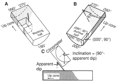
Figure 11. Conventions used for measuring azimuths and dips of structural features in the core and techniques used for measuring structural planes in three dimensions in the core reference frame. The core reference frame conventions for the working half and the archive half of the core can be seen in (A) and (B). The "E-W" (core reference frame) apparent dip of a feature was measured first and recorded as an apparent dip toward either 090° or 270° (in this case, the apparent dip is toward 090°). A second apparent dip was measured by making a cut parallel to the core axis, but perpendicular to the core face in the working half of the core (A). The feature was identified on the new surface, and the apparent dip in the "N-S" (core reference frame) direction was marked with a toothpick. The apparent dip was measured with a clinometer (C) and recorded as a value toward either 000° or 180°. In this diagram, the apparent dip is toward 180° (into the working half). True dip and strike of the surface in the core reference frame were calculated from the two apparent measurements.