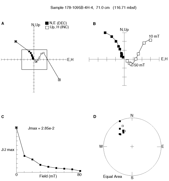
Figure F18. A. Vector end-point diagram showing the removal of the drill-string overprint at the 10-mT step for Sample 178-1095B-4H-4, 71 cm (166.71 mbsf). B. Enlarged view of the boxed region from A. A second component with a reversed polarity magnetization is removed between 10 and 50 mT. We interpret this as the primary remanence and construe the remaining normal polarity component as a probably more recent overprint. C. Change in the intensity of remanence during AF demagnetization. D. Equal-area projection of the remanence vector during AF demagnetization. DEC = declination, INC = inclination.

![]()