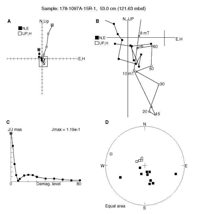
Figure F17. A. Orthogonal projection of the end-points of the remanence vector for Sample 178-1097A-15R-1, 53 cm. Open and solid symbols represent the vertical and horizontal projections, respectively. The drill-string overprint is removed at the 8-mT demagnetization step. B. Enlargement of boxed area in A, which shows that this sample has no stable direction of magnetization. C. Change in the intensity of remanence, normalized to the 0-mT (NRM) intensity, during AF demagnetization. D. Equal-area projection of the remanence vector during AF demagnetization.

![]()