![]()
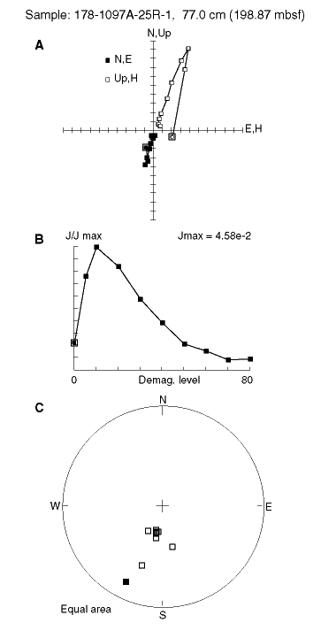
Figure F19. A. Orthogonal projection of the end-points of the remanence vector for Sample 178-1097A-25R-1, 77 cm. Open and solid symbols represent the vertical and horizontal projection, respectively. This sample displays the steep inclination expected for this site. B. Change in the intensity of remanence, normalized to the 0-mT (NRM) intensity, during AF demagnetization. C. Equal-area projection of the remanence vector during AF demagnetization.
![]()