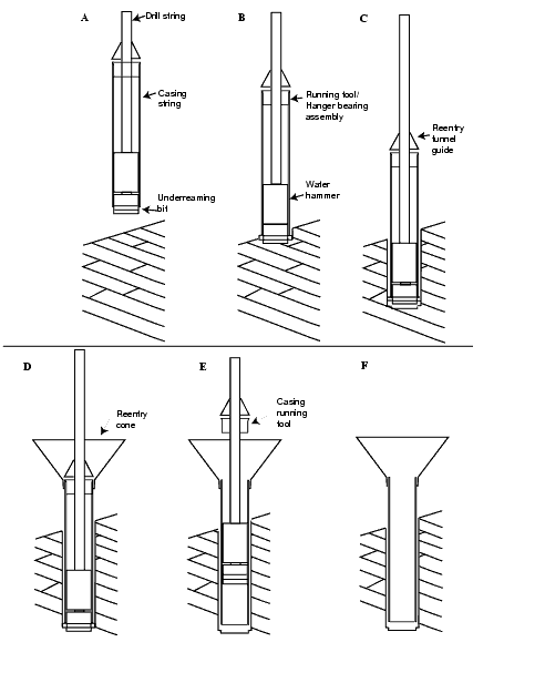
Figure F8. Schematic diagram of water hammer drill-in casing system deployment. A. Initial deployment. B. Spud hole and drill ahead. C. Disengage hydraulic hammer and circulate fluid. D. Install free-fall reentry funnel. E. Retract bit and release casing running tool. F. Recover hammer drill and leave a cased reentry hole on the seafloor.

![]()