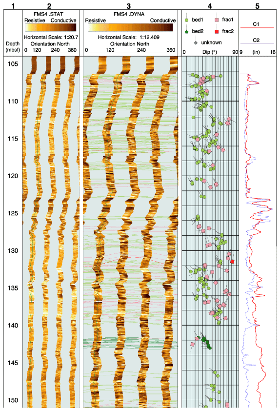
Figure AF1. FMS image and analysis, Hole 1114A. Vertical scale = 1/200. From left: (1) depth, (2) static FMS image, (3) dynamic FMS image with a 2-m color equalization sliding window with sinusoids corresponding to the structural measurements, (4) structural interpretation tadpoles, and (5) caliper measurements. The thin vertical green line on the FMS images indicates the orientation of pad 1, which correspond to the C1 caliper reading. The tadpole position on the horizontal axis indicates the dip magnitude, and its tail points toward the dip direction. (Continued on next three pages.)


![]()