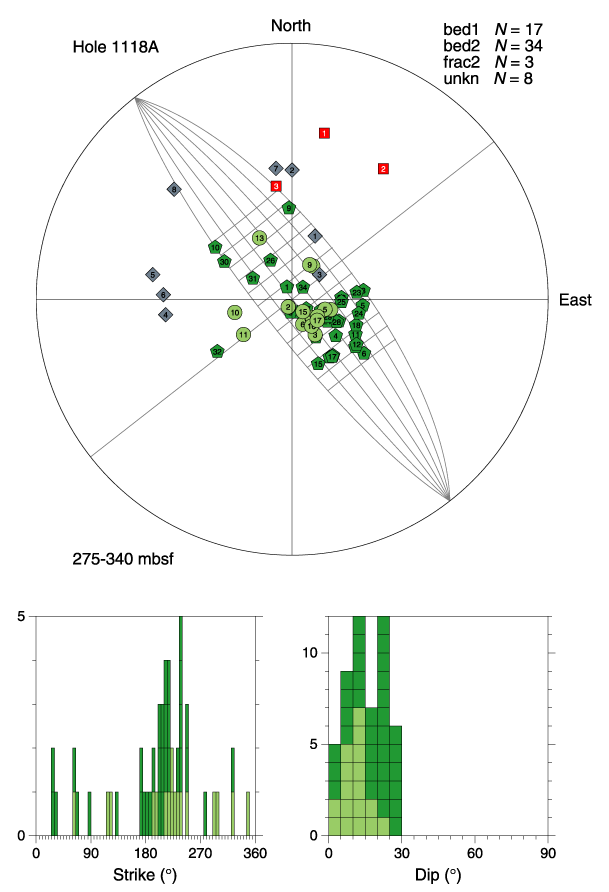
Figure F12. Structure orientations, Hole 1118A, 275-340 mbsf. Stereographic projection of poles to bed 1, bed 2, frac 2 (none in this interval), and unknown structures (light green circles, darker green pentagons, red squares, and gray diamonds, respectively). Equal area stereographic projection, lower hemisphere. Strike and dip histograms of bedding only, where bed 1 and bed 2 are stacked with same color code as stereonet poles. Histograms use 5° bins. Strike is normalized so that the dip direction is 90° clockwise from strike. A partial 5° stereonet is shown in the background to highlight a cylindrical structure.


![]()