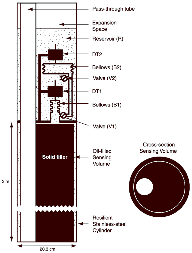
Figure F5. Schematic diagram for the dilatometer deployed in this experiment. The principle is the same as for the original design (Fig. F4) but significant modifications are required. The walls are thick enough to withstand the high pressure at the installation depth. An open tube allows cement to be pumped through the instrument. The sensing volume is nearly filled with solid aluminum to decrease the volume of oil (see cross section). This lowers the thermal sensitivity of the sensor and decreases loss of sensitivity due to the oil's compressibility. We also incorporate a second bellows-differential transformer-valve assembly to ensure no data loss when the valves are opened to equilibrate the instrument; only one valve can be open at a time. DT = differential transformer.

![]()