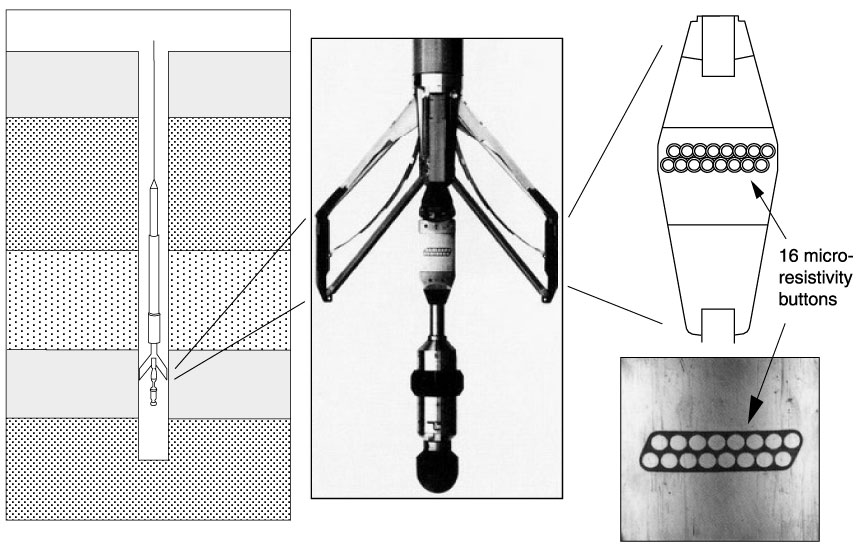
Figure F13. Schematic diagram showing the FMS tool downhole. The enlarged portion shows a photograph of the FMS caliper arms on which the microelectrode arrays are extended. The FMS electrode pad with 16 buttons used for microresistivity imaging of the borehole wall is also shown.
![]()