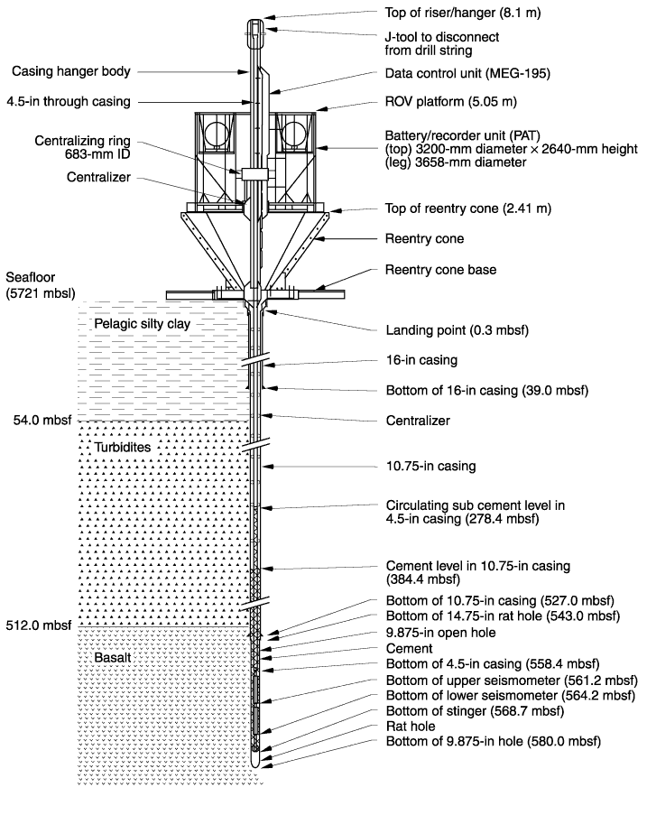
Figure F90.
Borehole instrument assembly (BIA) installation schematic. The BIA hangs on a
4.5-in casing pipe, which in turn hangs on the riser hanger support just below
the reentry cone. The cables from the sensors are strapped to the casing pipe
with tie wraps and duct tape and protected by centralizers. Cement is pumped
through the 4.5-in casing pipe and the BIA and out the bottom of the stinger.
Cement is pumped to completely fill the open borehole and to extend into a lower
part of the 10.75-in casing. The sensors are thus strongly coupled to the bare
rock. PAT = power access terminal. MEG = multiple-access expandable gateway, ROV
= remotely operated vehicle.


![]()