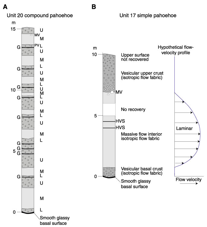
Figure F13. Examples of the characteristic internal architecture of (A) compound pahoehoe (Unit 20) and (B) simple pahoehoe lava flows (Unit 17) at Site 1205. In detail, the arrangements of lobe structures in Unit 20 are identical to those shown for Unit 17. Also shown is a inferred flow-velocity profile for an inflated pahoehoe lobe. G = lobe margins, U = upper vesicular crust, M = massive lobe interior, L = lower vesicular crust, MV = megavesicles, PV = pipe vesicles, HVS = horizontal vesicle sheets (i.e., segregation veins).