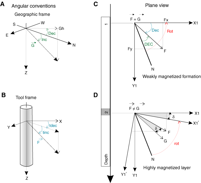
Figure F1. Angular conventions and tool orientation determination. A. In the geographic frame the geomagnetic field vector ( ) is described in terms of intensity (G), magnetic declination (Dec = angle formed between true north [N] and the projection of
  on the horizontal plane), and magnetic inclination (Inc, also called magnetic dip = angle measured from the horizontal plane positively down to the magnetic field vector). B. In the tool frame, the local total magnetic field (
 ) is described in terms of intensity (F), declination (tdec), and inclination (tinc). C. In plane view, estimation of the tool orientation, related to the instantaneous rotation of the tool with respect to N, is made by comparing the declination (Dec) of the local magnetic field to the tabulated declination (DEC) of the geomagnetic field (see Table T1
for details on notation). D. When highly magnetized layers are present in the formation, the measured declination of the total magnetic field
  is different from the theoretical value of the geomagnetic field (G) by an angle (
 ) leading to an equal bias in the local estimation of tool rotation. X1 = real orientation of the tool x-axis, X1' = apparent orientation of the tool.


 ) leading to an equal bias in the local estimation of tool rotation. X1 = real orientation of the tool x-axis, X1' = apparent orientation of the tool.

![]()