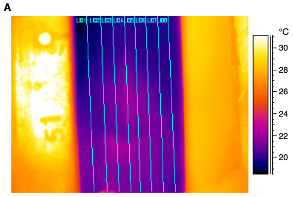
Figure F11. A. Different lines used to create core liner profile for Core 201-1226B-13H. Lines are numbered 1-8 from left. The 5-cm mark (white circle) is visible on the scale to the left (see"Infrared Thermal Imaging" in "Physical Properties" in the "Explanatory Notes" chapter). B. Different core liner temperature profiles generated along the eight profile lines.