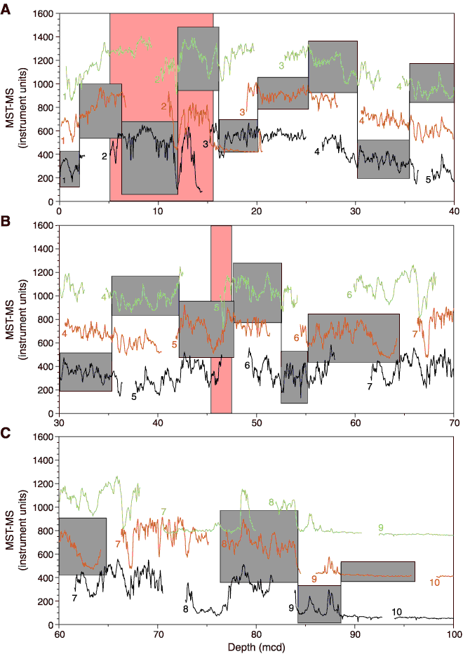
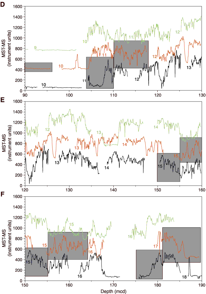
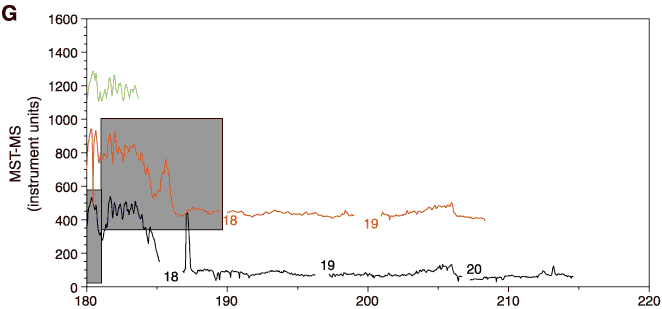
Figure F5. Magnetic susceptibility (MST-MS) vs. mcd for Holes 1235A through 1235C. Gray boxes indicate the portions of cores that are in the splice. Pink boxes indicate intervals within the splice of poor correlation between holes. A. 0-40 mcd. B. 30-70 mcd. C. 60-100 mcd. D. 90-130 mcd. E. 120-160 mcd. F. 150-190 mcd. G. 180-220
mcd.