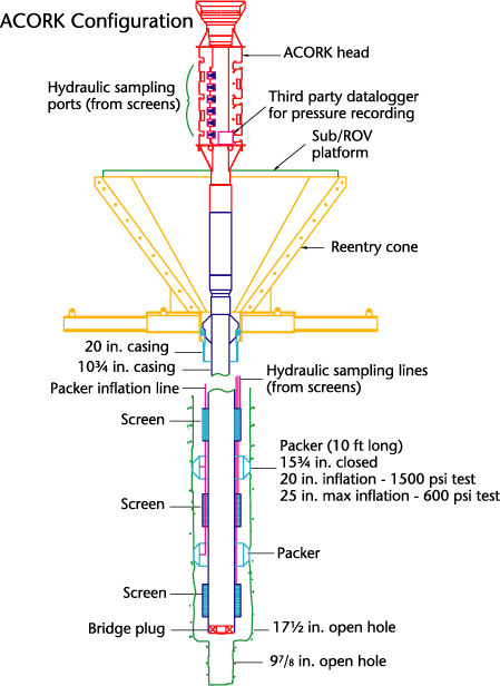
Figure 1. Schematic of
an ACORK installed in a reentry cone. The ACORK features downhole external
casing packers to seal off zones and screened sampling sections mounted on the
outside of the casing. The screened sections are connected by hydraulic sampling
tubing to the T-handle valves and ports (valve manifold) in the ACORK head. The
valve manifold allows pressure recording and fluid sampling. The ACORK head sits
above the reentry cone to allow the ROVs/submersibles access to sample and
download data.