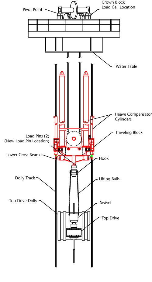
Figure 1.
Schematic of the upper derrick showing location of the load cell and load pins in relation to the crown block, heave compensator cylinders, and traveling block.