![]() Figures F1-F18
Figures F1-F18
![]() Tables
T1-T5
Tables
T1-T5
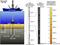
F1. Schematic illustrating hole, core, and section labeling.
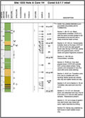
F2. Electronic visual core description form.
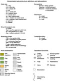
F3. Electronic volcaniclastic visual core description form key.
F4. Electronic volcaniclastic visual core description form.
F5. Electronic hard rock visual core description form key.
F6. Electronic hard rock visual core description form.
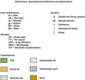
F7. Grain-size classification.
F8. AppleCORE sediment key.
F9. Smear slide description form.
F10. Thin section description form.
F11. Magnetic moment measured for an empty sample boat.
F12. Magnetic moment measured for an empty discrete sample tray sitting within the sample boat.
F13. ODP paleomagnetic coordinate system.
F14. Schematic illustration of tool string configurations.
F15. Summary of the significant dimensions necessary to correct the GPS location of various antennas to the moonpool.
F16. Significant depth dimensions on the ship.
F17. Significant depths and ranges for the single-channel seismic acquisition system and magnetometer system.
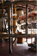
F18. The 4.252-kHz transducer, pinger batteries, and electronics on the VIT frame.
T1. ICP-AES analysis parameters.
T2. Typical values for USGS standards analyzed by ICP-AES.
T3. Logging tool and measurement units and acronyms.
T4. Logging tool specifications.
T5. WST-3 tool specifications.