![]() Figures F1-F20
Figures F1-F20
![]() Figures F21-F27
Figures F21-F27
![]() Tables T1-T8
Tables T1-T8
F1. Example of coring and depth intervals.
F2. Grain-size classification diagram for siliciclastic sediments.
F3. Classification scheme for siliciclastic sediment components.
F4. Example of VCDs.
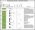
F5. Key to patterns and symbols used on barrel sheets.
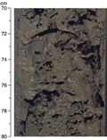
F6. Example of "soupy" sediment texture.
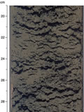
F7. Example of wet, watery, mousselike sediment texture associated with hydrate dissociation.
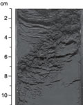
F8. Example of "flaky" mousselike texture associated with hydrate dissociation.
F9. Correlation of the GPTS and biostratigraphic zonations.
F10. FLIR SC-2000 camera.
F11. Typical gas hydrate shapes observed.
F12. GRA profile.
F13. Calibration plots for the NCR system.
F14. Gas expansion cracks.
F15. Typical APCT tool and DVTPP runs.
F16. PCS depressurization experiment.
F17. Drill string used for LWD operations.
F18. Rig instrumentation.
F19. The RAB tool.
F20. The RAB-8 tool.
![]() Figures F1-F20
Figures F1-F20
![]() Figures F21-F27
Figures F21-F27
![]() Tables T1-T8
Tables T1-T8