![]() Figures F1-F22
Figures F1-F22
F1. Schematic of an OsmoSampler.
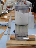
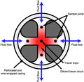
F2. Osmotic pump.
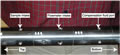
F3. Osmotic pump and several Teflon sampling coils.
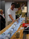
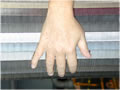
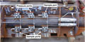
F4. Osmotic pump and a copper sampling coil.
![]()
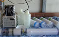
F5. Assembly of an OsmoSampler package.
F6. Sampling section of the intake probe, Hole 1255A.
F7. Schematic of an OsmoFlowmeter.
F8. Intake configuration for OsmoSampler and OsmoFlowmeter.
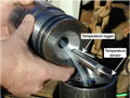
F9. Temperature data logger.
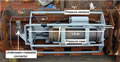
F10. Data logger bay of the CORK-II head.
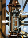
F11. CORK-II head bay with pressure sensor and data logger.
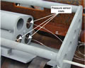
F12. Pressure sensor inlets.
F13. Wrapped screen.
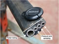
F14. Umbilical for packer inflation and sampling tubing.
F15. Centralizer and umbilical strapped onto the 4 -in casing.
F16. Schematic of the plumbing system of the CORK-II.
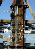
F17. CORK-II head plumbing and valve bay.
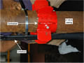
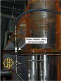
F18. Packer inflation tubing and quick release.
F19. CORK-II head latch and seal.
F20. CORK-II head bay with plumbing and valves.
F21. Hole 1253A CORK-II OsmoSampler installation space-out.
F22. Hole 1255A CORK-II OsmoSampler installation space-out.