Figure thumbnails 1-20
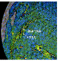
F1. Satellite altimetry free-air gravity map displaying the SWIR, the AII F.Z., and the location of Hole 735B.
F2. Bathymetry of the Atlantis II transform fault.
F3. Three-dimensional image of the Atlantis II transform fault.
F4. Schematic model showing the mechanism of exposure of gabbroic rock at Site 735.
F5. Detailed bathymetry of the Atlantis Bank adjacent to the Atlantis II transform fault.
F6. Three-dimensional shaded-relief image of the Atlantis Bank along the wall of the Atlantis II transform fault.
F7. Typical ophiolite stratigraphy juxtaposed against predictions of geophysical studies of slow-spreading ridge.
F8. Schematic diagram of water hammer drill-in casing system deployment.
F9. Schematic drawings of hammer drill concentric and eccentric underreamer bits.
F10. Schematic drawing of the SDS water hammer drill.
F11. Schematic drawing of the HDS running tool.
F12. Schematic drawing of the HDS go-devil.
F13. Schematic drawing of the HDS hanger bearing assembly.
F14. Schematic drawing of the HDS reentry cone assembly.
F15. SDS concentric underreamer bit 1.
F16. SDS concentric underreamer bit 2.
F17. SDS concentric underreamer bit modification 3.
F18. Holte concentric under-reamer bit.
F19. Holte eccentric underreamer bit.
F20. SDS drilling bit, p. 92.