![]() Figures F1-F29
Figures F1-F29
![]() Tables
T1-T7
Tables
T1-T7
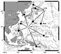
F1. Location map of seismic station coverage in the northwest Pacific.
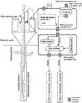
F2. Schematic view of the NEREID-191 system of the WP-2 borehole seismological observatory.
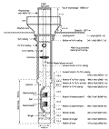
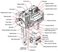
F3. Borehole instrumentation assembly installation schematic.
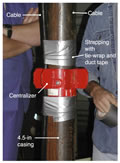
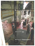
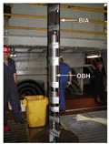
F4. Cable strappings and centralizer.
F5. Borehole instrumentation assembly placement.
F6. Appearance of the borehole instrumentation assembly.
F7. An OBH sensor emplaced on the borehole instrument assembly.
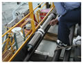
F8. Cable connections to the OBH during BIA installation.
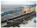
F9. Installation of the BIA in the moonpool area.
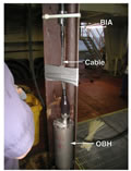
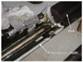
F10. Insulation between the OBH sensors and the BIA.
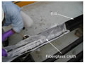
F11. Fiberglass cloth glued over the surfaces of the BIA.
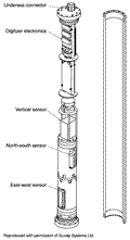
F12. Components of the ocean borehole seismometer used for Leg 191 installation.
F13. Drawing of the CMG-1T vertical sensor.
F14. Schematic diagram for the electronic circuits of the CMG-1T sensors.
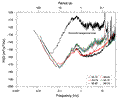
F15. Spectra of instrument self noise for horizontal components of the OBHs.
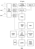
F16. Schematic diagram of the DM24 digitizer.
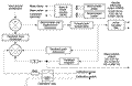
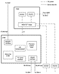
F17. MEG-191 system block diagram.
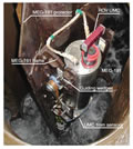
F18. Photograph showing the MEG-191 installed in the MEG frame.
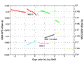
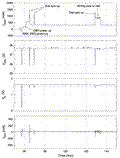
F19. Example showing the results of the time difference measurement between the MEG-191 and the SAM-191.
F20. Schematic diagram of the seawater battery system.
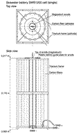
F21. Seawater battery cell structure.
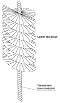
F22. Structure of the carbon fiber brush used in the cell cathode.
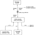
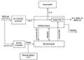
F23. Block diagram of the power control system.
F24. Voltages and currents measured by the power control system.
![]()
F25. Variation of voltages and currents in the seawater battery system.
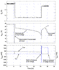
F26. Records from the power control system during the final equipment test.
F27. Photograph of the power access terminal in the moonpool area.

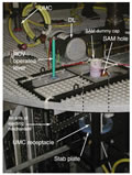
F28. Photograph of the recorder frame of the storage acquisition module with a dummy cap.
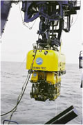
F29. ROV Kaiko, which activated the NEREID-191 in October 2000.
T1. Glossary of the NEREID-191 system.
T2. Mapping between sensor channels and stream ID in GCF.
T3. Explanation of status messages from the CRM in the MEG/SAM.
T4. Available command set in the CRM, OBH, and SAM.
T5. Pin assignments of underwater mateable stab plate connectors.
T6. Data storage estimation for the seismic observatory.
T7. Power consumption of the NEREID-191 system.