![]() Figures F1-F20
Figures F1-F20
![]() Figures F21-F40
Figures F21-F40
![]() Figures
F41-F51
Figures
F41-F51
![]() Table T1-T22
Table T1-T22
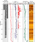
F41. CWL data.
F42. CWL gamma ray data.
F43. Comparison of LWD and CWL.
F44. CWL acoustic logging data.

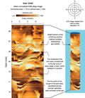
F45. RAB image showing the presence of gas hydrate.
F46. RAB and FMS images showing an ash layer.
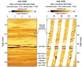
F47. RAB and FMS images showing turbidites.

F48. RAB image showing borehole breakouts.

F49. Comparison of LWD and core-derived porosities.

F50. LWD-derived water saturations.
F51. Borehole temperatures recorded with the TAP tool.
T1. Coring summary.
T2. Presence of gas hydrate based on IR images.
T3. Bioevents.
T4. IW data.
T5. Concentrations of dissolved chloride and sulfate.
T6. Concentrations of C1, C2, and C3.
T7. Concentrations of C1, C2, and C3 in VAC samples.
T8. Headspace methane.
T9. Gas from decomposition of gas hydrate.
T10. Gas composition of samples from the PCS experiments.
T11. IC, OC, TN, and TS contents and C/N ratios.
T12. Rock-Eval pyrolysis of samples.
T13. Intervals sampled for microbiology.
T14. Core quality indicators.
T15. MAD sample values.
T16. VP values from split-core analyses.
T17. Thermal conductivity.
T18. Shear strength values.
T19. Temperature measurements.
T20. Results from degassing experiments.
T21. HYACINTH coring summary.
T22. CWL operations summary.
![]() Figures F1-F20
Figures F1-F20
![]() Figures F21-F40
Figures F21-F40
![]() Figures
F41-F51
Figures
F41-F51
![]() Table T1-T22
Table T1-T22